Radiated Emissions Test Systems
EMI receivers for radiated emissions measurement, paired with an antenna and chamber.
Radiated emissions testing measures the unintentional RF energy a device emits into free space — energy that could interfere with other equipment or communications systems if left unchecked. The measurement instrumentation for this task turns out to be the same core equipment used for conducted emissions measurement, paired with an antenna and a suitable test environment, rather than an entirely separate measurement discipline requiring different fundamental instruments.
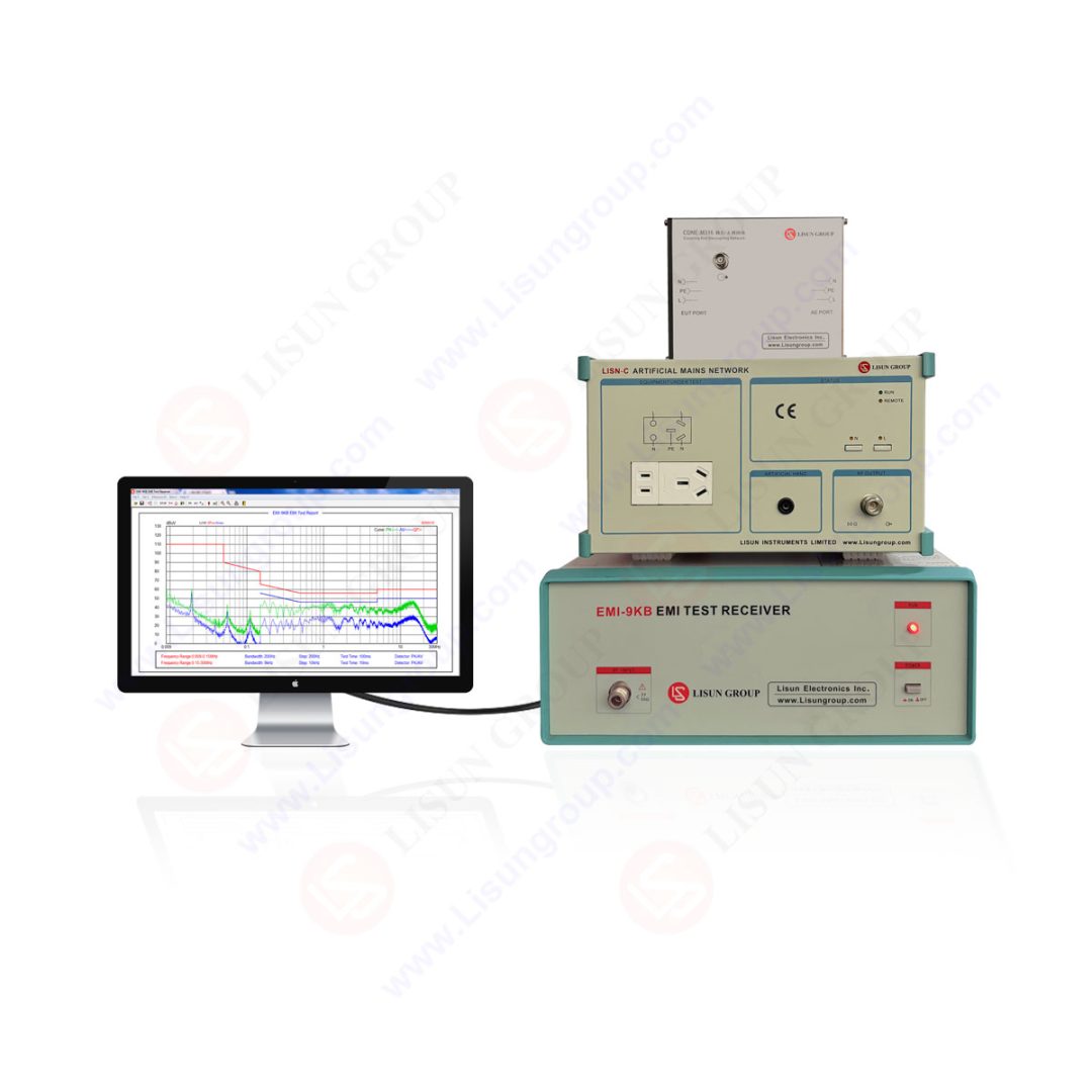
An EMI receiver forms the core of a radiated emissions measurement setup, connected to a calibrated antenna positioned to capture the device's radiated emissions, typically within a semi-anechoic chamber or similarly controlled RF environment that keeps external interference from corrupting the measurement. Because the same EMI receiver instrumentation serves both radiated and conducted emissions measurement, a lab investing in receiver capability gets shared infrastructure across both test disciplines rather than needing entirely separate receiver equipment for each.
This shared-infrastructure characteristic is a practical consideration for any lab building out EMC test capability — the EMI receiver investment supports both radiated and conducted emissions work, with the antenna, chamber, and coupling equipment being the discipline-specific additions on top of that shared receiver foundation.
Frequently Asked Questions
Why does the same EMI receiver work for both radiated and conducted emissions testing?
The EMI receiver's core job — accurately measuring signal level across a specified frequency range with the detector characteristics standards like CISPR require — is the same underlying measurement task in both disciplines. What differs is what feeds into the receiver: an antenna for radiated emissions, or a LISN/coupling network for conducted emissions.
What test environment does radiated emissions measurement typically require?
A semi-anechoic chamber or similarly controlled RF environment is typically needed to prevent external ambient RF signals from corrupting the measurement of the device under test's own emissions — an open test site or unshielded room would pick up interference the chamber is built to exclude.
Does investing in radiated emissions capability also support conducted emissions testing?
Largely yes — since the EMI receiver instrumentation is shared between the two disciplines, a lab equipped for radiated emissions measurement already has the core receiver capability needed for conducted emissions work, needing only the additional LISN and coupling network hardware specific to conducted measurement.