Output up to 690Vrms and 800VA, Bandwidth (-3dB) 10kHz-500kHz, drives 0-100% resistive or non-resistive loads
Driving a load that isn't a clean, fixed resistance — anything from a partially reactive test load to a device whose impedance shifts across its operating range — needs an amplifier that can adapt its output impedance matching rather than assuming a fixed, purely resistive load throughout. Aigtek's ATA-M Series addresses this directly: a single-channel amplifier built to drive loads across the full 0-100% resistive-to-non-resistive range, with output impedance matching adjustable via multiple taps.
Maximum output voltage of 690Vrms and 800VA output power give the ATA-M substantial drive capability, with bandwidth spanning 10kHz to 500kHz (-3dB) covering a solid mid-to-high frequency range for demanding load-driving applications. Built-in protection against over-temperature, over-voltage, short-circuit and no-load conditions adds a layer of safety for test setups where load characteristics may not be perfectly predictable in advance, with the protection status shown on the LCD.
The adjustable impedance matching taps let a test engineer configure the amplifier's output matching to suit the specific load being driven, rather than accepting a fixed matching configuration that may not be optimal across every load type the amplifier is asked to handle.
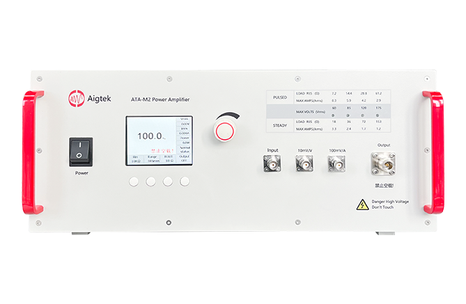
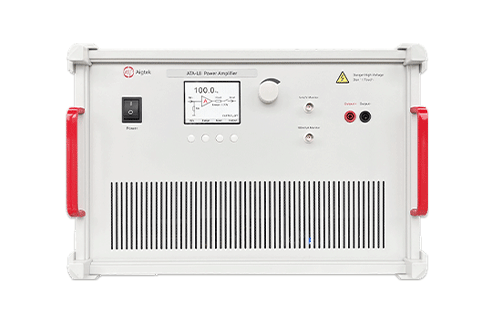
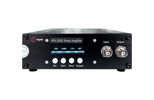
| Model | Bandwidth (-3dB) | Voltage | Power | Channel | |
|---|---|---|---|---|---|
| ATA-M2 | 10kHz-500kHz | 175Vrms | 200VA | Single | Enquire |
| ATA-M4 | 10kHz-500kHz | 345Vrms | 400VA | Single | Enquire |
| ATA-M8 | 10kHz-500kHz | 690Vrms | 800VA | Single | Enquire |
The ATA-M2 is a single-channel power amplifier with a maximum output voltage of 175Vrms and continuous power of 200VA (pulse up to 500VA). It can drive 0~100% of both resistive and non-resistive loads, and its output impedance is matched across multiple selectable ranges to suit specific test requirements.
| Model | ATA-M2 |
| Bandwidth (-3dB) | 10kHz~500kHz |
| Maximum Output Voltage | 175Vrms |
| Maximum Continuous Output Power | 200VA |
| Maximum Pulse Output Power | 500VA, 10% @ 1s |
| Total Harmonic Distortion (THD) | ≤0.5% @ 50kHz, 42Vrms (85Vrms range) |
| Input Voltage for Full-Scale Output | 1Vrms |
| Input Impedance | 10kΩ |
| Voltage Monitoring | 10mV/V (±5% @ Output, FS) |
| Current Monitoring | 100mV/A (±5% @ Output, FS) |
| Output Interface | N-type connector |
| Protection | Over Temperature, Over Voltage, Short Circuit and No Load Protection |
| Signal Ground | Connected to chassis and power line ground |
| Others | |
| Power Supply Voltage | AC110~240V, 50/60Hz |
| Operating Temperature | 0°C~45°C |
| Storage Temperature | -20°C~50°C |
| Working Humidity | ≤80% RH, non-condensing |
| Warranty | 1 year |
Download the full technical datasheet for the ATA-M2, published by Aigtek.
⬇ Download Datasheet (PDF) Enquire About ATA-M2 →The ATA-M4 is a single-channel power amplifier with a maximum output voltage of 345Vrms and continuous power of 400VA (pulse up to 1000VA). It can drive 0~100% of both resistive and non-resistive loads, and its output impedance is matched across multiple selectable ranges to suit specific test requirements.
| Model | ATA-M4 |
| Bandwidth (-3dB) | 10kHz~500kHz |
| Maximum Output Voltage | 345Vrms |
| Maximum Continuous Output Power | 400VA |
| Maximum Pulse Output Power | 1000VA, 10% @ 1s |
| Total Harmonic Distortion (THD) | ≤0.5% @ 50kHz, 42Vrms (85Vrms range) |
| Input Voltage for Full-Scale Output | 1Vrms |
| Input Impedance | 10kΩ |
| Voltage Monitoring | 10mV/V (±5% @ Output, FS) |
| Current Monitoring | 100mV/A (±5% @ Output, FS) |
| Output Interface | N-type connector |
| Protection | Over Temperature, Over Voltage, Short Circuit and No Load Protection |
| Signal Ground | Connected to chassis and power line ground |
| Others | |
| Power Supply Voltage | AC110~240V, 50/60Hz |
| Operating Temperature | 0°C~45°C |
| Storage Temperature | -20°C~50°C |
| Working Humidity | ≤80% RH, non-condensing |
| Warranty | 1 year |
| Dimensions | 440×194×455mm (W×H×D) |
Download the full technical datasheet for the ATA-M4, published by Aigtek.
⬇ Download Datasheet (PDF) Enquire About ATA-M4 →Real-world test loads often aren't purely resistive — they can include reactive (capacitive or inductive) components in varying proportions. The ATA-M's rated ability to drive loads across this full spectrum means it isn't limited to purely resistive test setups, covering a wider range of practical load conditions than an amplifier specified only for resistive loads.
Matching the amplifier's output impedance to the load's characteristic impedance affects power transfer efficiency and signal fidelity. Multiple adjustable taps let the matching be tuned to the specific load in use, rather than accepting a single fixed matching point that may only be optimal for one particular load configuration.
The ATA-M2 and ATA-M4 include over-temperature, over-voltage, short-circuit and no-load protection. The LCD shows the current protection status, and output resumes only once the fault has been cleared.